 English
 |


| Quantity: | |
|---|---|
xzwd
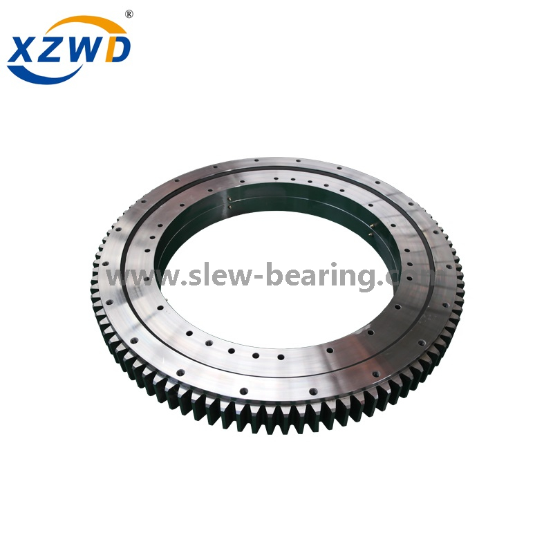
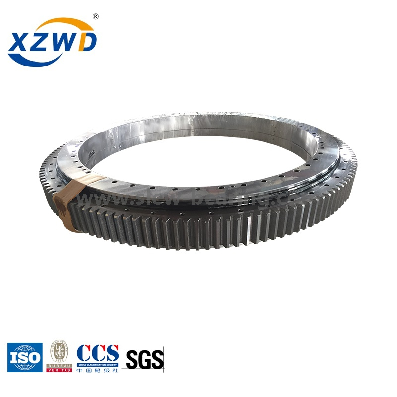
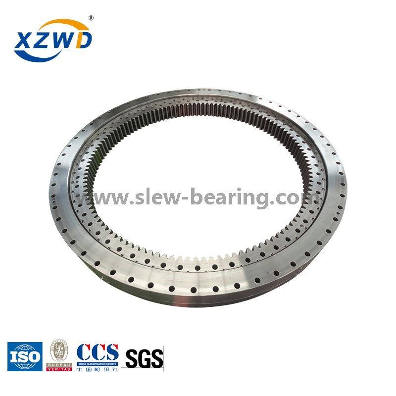
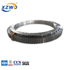
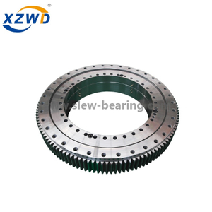
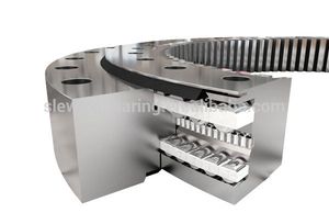
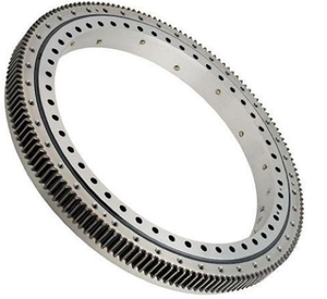
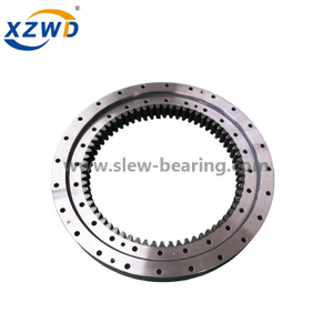
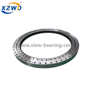
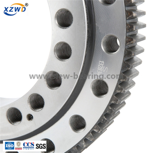
XZWD 13 series three-row roller slewing bearing offer the highest capacity for a given diameter. When an 01 series or 02 series bearing doesn't meet your stiffness and capacity requirements, consider the 13 series, offering a wide variety of solutions for radar, cranes, mining shovels, and other applications.
Design features
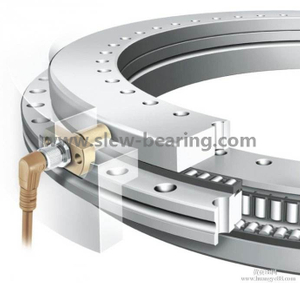
The 13 series bearing has three independent rows of rollers oriented normal to the direction of loads being transmitted through the bearing. Their orientation is selected to optimize capacity, provide low frictional resistance and minimize deflection.
The top and bottom rows of rollers transmit any opposing thrust loads and combine to transmit any moment loading, while the middle row transmits any radial loads. The rollers, the separator configuration used for each, and the mating raceways are sized to meet load or other application requirements.
In order to obtain these performance benefits, the supporting structures must satisfy higher stiffness and lower flatness requirements than those for similar sized 01 or 02 series bearings.
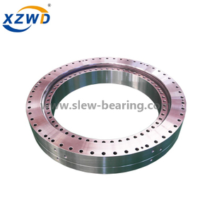
Gear teeth or other drive mechanisms can be provided on the inner or outer support ring, and the choice of hole pattern can be added for bearing retention.
Availability
13 series slewing ring bearings are custom manufactured to fit the design and specification.
Applications
13 series bearings have been used successfully in heavy-duty applications requiring extra stiffness and capacity including:
· Radar
· Cranes
· Mining shovels
· Stackers and reclaimers
· Heavy mill equipment
· Tunnel boring machines
To get drawing (pdf),please clik on Model.
No. | Inxternal Gear | Dimensions | Mounting Dimension | Structural Dimension | Gear Data | Gear circumferential force | Weight | ||||||||||||||
D | d | H | D1 | D2 | n | mm | dm | L | n1 | H1 | h | b | x | m | D e | z | Normalizing | Quenching | |||
1 |
| 634 | 366 | 148 | 598 | 402 | 24 | 18 | M16 | 32 | 4 | 10 | 32 | 80 | 0.5 | 5 | 337 | 68 | 5.0 | 6.7 | 224 |
134.25.500 | 6 | 338.4 | 57 | ||||||||||||||||||
2 |
| 694 | 426 | 148 | 658 | 462 | 24 | 18 | M16 | 32 | 4 | 10 | 32 | 80 | 0.5 | 5 | 397 | 80 | 5.0 | 6.7 | 240 |
134.25.560 | 6 | 398.4 | 67 | ||||||||||||||||||
3 |
| 764 | 496 | 148 | 728 | 532 | 28 | 18 | M16 | 32 | 4 | 10 | 32 | 80 | 0.5 | 6 | 458.4 | 77 | 6.0 | 8 | 270 |
134.25.630 | 8 | 459.2 | 58 | ||||||||||||||||||
4 |
| 844 | 576 | 148 | 808 | 612 | 28 | 18 | M16 | 32 | 4 | 10 | 32 | 80 | 0.5 | 6 | 536.4 | 90 | 6.0 | 8 | 300 |
134.25.710 | 8 | 539.2 | 68 | ||||||||||||||||||
5 |
| 964 | 636 | 182 | 920 | 680 | 36 | 22 | M20 | 40 | 4 | 10 | 40 | 120 | 0.5 | 8 | 595.2 | 75 | 12.1 | 16.7 | 500 |
134.32.800 | 10 | 594 | 60 | ||||||||||||||||||
6 |
| 1064 | 736 | 182 | 1020 | 780 | 36 | 22 | M20 | 40 | 4 | 10 | 40 | 120 | 0.5 | 8 | 691.2 | 87 | 12.1 | 16.7 | 600 |
134.32.900 | 10 | 694 | 70 | ||||||||||||||||||
7 | 1164 | 836 | 182 | 1120 | 880 | 40 | 22 | M20 | 40 | 5 | 10 | 40 | 120 | 0.5 | 10 | 784 | 79 | 15.1 | 20.9 | 680 | |
134.32.1000 | 12 | 784.8 | 66 | ||||||||||||||||||
8 | 1284 | 956 | 182 | 1240 | 1000 | 40 | 22 | M20 | 40 | 5 | 10 | 40 | 120 | 0.5 | 10 | 904 | 91 | 15.1 | 20.9 | 820 | |
134.32.1120 | 12 | 904.8 | 76 | ||||||||||||||||||
9 | 1445 | 1055 | 220 | 1393 | 1107 | 45 | 26 | M24 | 48 | 5 | 10 | 50 | 150 | 0.5 | 12 | 988.8 | 83 | 22.9 | 31.4 | 1200 | |
134.40.1250 | 14 | 985.6 | 71 | ||||||||||||||||||
10 | 1595 | 1205 | 220 | 1543 | 1257 | 45 | 26 | M24 | 48 | 5 | 10 | 50 | 150 | 0.5 | 12 | 1144.8 | 96 | 22.9 | 31.4 | 1300 | |
134.40.1400 | 14 | 1139.6 | 82 | ||||||||||||||||||
11 | 1795 | 1405 | 220 | 1743 | 1457 | 48 | 26 | M24 | 48 | 6 | 10 | 50 | 150 | 0.5 | 14 | 1335.6 | 96 | 26.3 | 36.6 | 1520 | |
134.40.1600 | 16 | 1334.4 | 84 | ||||||||||||||||||
12 | 1995 | 1605 | 220 | 1943 | 1657 | 48 | 26 | M24 | 48 | 6 | 10 | 50 | 150 | 0.5 | 14 | 1531.6 | 110 | 26.3 | 36.6 | 1750 | |
134.40.1800 | 16 | 1526.4 | 96 | ||||||||||||||||||
13 | 133.45.2000 | 2221 | 1779 | 231 | 2155 | 1845 | 60 | 33 | M30 | 60 | 6 | 12 | 54 | 160 | 0.5 | 16 | 1702.4 | 107 | 32.2 | 44.5 | 2400 |
134.45.2000 | 18 | 1699.2 | 95 | ||||||||||||||||||
14 | 133.45.2240 | 2461 | 2019 | 231 | 2395 | 2085 | 60 | 33 | M30 | 60 | 6 | 12 | 54 | 160 | 0.5 | 16 | 1926.4 | 121 | 32.2 | 44.5 | 2700 |
134.45.2240 | 18 | 1933.2 | 108 | ||||||||||||||||||
15 | 133.45.2500 | 2721 | 2279 | 231 | 2655 | 2345 | 72 | 33 | M30 | 60 | 8 | 12 | 54 | 160 | 0.5 | 18 | 2185.2 | 122 | 36.2 | 50.1 | 3000 |
134.45.2500 | 20 | 2188 | 110 | ||||||||||||||||||
16 | 133.45.2800 | 3021 | 2579 | 231 | 2955 | 2645 | 72 | 33 | M30 | 60 | 8 | 12 | 54 | 160 | 0.5 | 18 | 2491.2 | 139 | 36.2 | 50.1 | 3400 |
134.45.2800 | 20 | 2488 | 125 | ||||||||||||||||||
17 | 133.50.3150 | 3432 | 2868 | 270 | 3342 | 2958 | 72 | 45 | M42 | 84 | 8 | 12 | 65 | 180 | 0.5 | 20 | 2768 | 139 | 45.2 | 62.6 | 5000 |
134.50.3150 | 22 | 2758.8 | 126 | ||||||||||||||||||
18 | 133.50.3550 | 3832 | 3268 | 270 | 3742 | 3358 | 72 | 45 | M42 | 84 | 8 | 258 | 65 | 180 | 0.5 | 20 | 3168 | 159 | 45.2 | 62.6 | 5680 |
134.50.3500 | 22 | 3154.8 | 144 | 49.8 | 68.9 | ||||||||||||||||
19 | 133.50.4000 | 4282 | 3718 | 270 | 4192 | 3808 | 80 | 45 | M42 | 84 | 8 | 258 | 65 | 180 | 0.5 | 22 | 3116.8 | 165 | 49.8 | 68.9 | 6470 |
134.50.4000 | 25 | 3610 | 145 | 56.5 | 78.3 | ||||||||||||||||
20 | 133.50.4500 | 4782 | 4218 | 270 | 4692 | 4308 | 80 | 45 | M42 | 84 | 8 | 258 | 65 | 180 | 0.5 | 22 | 4122.8 | 188 | 49.8 | 68.9 | 7320 |
134.50.4500 | 25 | 4110 | 165 | 56.5 | 78.3 | ||||||||||||||||
Note:
1. N1 is the numbers of lubricating holes. Oil cup M10×1JB/T7940.1~JB/T7940.
2. The Oil nipple's location can be change according to the user's application.
2. n-φ can change to tapped hole, the diameter of tapped hole is M, and depth is 2M.
3. The tangential tooth force in the form is the max tooth force; the nominal tangential tooth force is 1/2 of the max one.
4. "K" is addendum reduction coefficient.
XZWD 13 series three-row roller slewing bearing offer the highest capacity for a given diameter. When an 01 series or 02 series bearing doesn't meet your stiffness and capacity requirements, consider the 13 series, offering a wide variety of solutions for radar, cranes, mining shovels, and other applications.
Design features
The 13 series bearing has three independent rows of rollers oriented normal to the direction of loads being transmitted through the bearing. Their orientation is selected to optimize capacity, provide low frictional resistance and minimize deflection.
The top and bottom rows of rollers transmit any opposing thrust loads and combine to transmit any moment loading, while the middle row transmits any radial loads. The rollers, the separator configuration used for each, and the mating raceways are sized to meet load or other application requirements.
In order to obtain these performance benefits, the supporting structures must satisfy higher stiffness and lower flatness requirements than those for similar sized 01 or 02 series bearings.
Gear teeth or other drive mechanisms can be provided on the inner or outer support ring, and the choice of hole pattern can be added for bearing retention.
Availability
13 series slewing ring bearings are custom manufactured to fit the design and specification.
Applications
13 series bearings have been used successfully in heavy-duty applications requiring extra stiffness and capacity including:
· Radar
· Cranes
· Mining shovels
· Stackers and reclaimers
· Heavy mill equipment
· Tunnel boring machines
To get drawing (pdf),please clik on Model.
No. | Inxternal Gear | Dimensions | Mounting Dimension | Structural Dimension | Gear Data | Gear circumferential force | Weight | ||||||||||||||
D | d | H | D1 | D2 | n | mm | dm | L | n1 | H1 | h | b | x | m | D e | z | Normalizing | Quenching | |||
1 |
| 634 | 366 | 148 | 598 | 402 | 24 | 18 | M16 | 32 | 4 | 10 | 32 | 80 | 0.5 | 5 | 337 | 68 | 5.0 | 6.7 | 224 |
134.25.500 | 6 | 338.4 | 57 | ||||||||||||||||||
2 |
| 694 | 426 | 148 | 658 | 462 | 24 | 18 | M16 | 32 | 4 | 10 | 32 | 80 | 0.5 | 5 | 397 | 80 | 5.0 | 6.7 | 240 |
134.25.560 | 6 | 398.4 | 67 | ||||||||||||||||||
3 |
| 764 | 496 | 148 | 728 | 532 | 28 | 18 | M16 | 32 | 4 | 10 | 32 | 80 | 0.5 | 6 | 458.4 | 77 | 6.0 | 8 | 270 |
134.25.630 | 8 | 459.2 | 58 | ||||||||||||||||||
4 |
| 844 | 576 | 148 | 808 | 612 | 28 | 18 | M16 | 32 | 4 | 10 | 32 | 80 | 0.5 | 6 | 536.4 | 90 | 6.0 | 8 | 300 |
134.25.710 | 8 | 539.2 | 68 | ||||||||||||||||||
5 |
| 964 | 636 | 182 | 920 | 680 | 36 | 22 | M20 | 40 | 4 | 10 | 40 | 120 | 0.5 | 8 | 595.2 | 75 | 12.1 | 16.7 | 500 |
134.32.800 | 10 | 594 | 60 | ||||||||||||||||||
6 |
| 1064 | 736 | 182 | 1020 | 780 | 36 | 22 | M20 | 40 | 4 | 10 | 40 | 120 | 0.5 | 8 | 691.2 | 87 | 12.1 | 16.7 | 600 |
134.32.900 | 10 | 694 | 70 | ||||||||||||||||||
7 | 1164 | 836 | 182 | 1120 | 880 | 40 | 22 | M20 | 40 | 5 | 10 | 40 | 120 | 0.5 | 10 | 784 | 79 | 15.1 | 20.9 | 680 | |
134.32.1000 | 12 | 784.8 | 66 | ||||||||||||||||||
8 | 1284 | 956 | 182 | 1240 | 1000 | 40 | 22 | M20 | 40 | 5 | 10 | 40 | 120 | 0.5 | 10 | 904 | 91 | 15.1 | 20.9 | 820 | |
134.32.1120 | 12 | 904.8 | 76 | ||||||||||||||||||
9 | 1445 | 1055 | 220 | 1393 | 1107 | 45 | 26 | M24 | 48 | 5 | 10 | 50 | 150 | 0.5 | 12 | 988.8 | 83 | 22.9 | 31.4 | 1200 | |
134.40.1250 | 14 | 985.6 | 71 | ||||||||||||||||||
10 | 1595 | 1205 | 220 | 1543 | 1257 | 45 | 26 | M24 | 48 | 5 | 10 | 50 | 150 | 0.5 | 12 | 1144.8 | 96 | 22.9 | 31.4 | 1300 | |
134.40.1400 | 14 | 1139.6 | 82 | ||||||||||||||||||
11 | 1795 | 1405 | 220 | 1743 | 1457 | 48 | 26 | M24 | 48 | 6 | 10 | 50 | 150 | 0.5 | 14 | 1335.6 | 96 | 26.3 | 36.6 | 1520 | |
134.40.1600 | 16 | 1334.4 | 84 | ||||||||||||||||||
12 | 1995 | 1605 | 220 | 1943 | 1657 | 48 | 26 | M24 | 48 | 6 | 10 | 50 | 150 | 0.5 | 14 | 1531.6 | 110 | 26.3 | 36.6 | 1750 | |
134.40.1800 | 16 | 1526.4 | 96 | ||||||||||||||||||
13 | 133.45.2000 | 2221 | 1779 | 231 | 2155 | 1845 | 60 | 33 | M30 | 60 | 6 | 12 | 54 | 160 | 0.5 | 16 | 1702.4 | 107 | 32.2 | 44.5 | 2400 |
134.45.2000 | 18 | 1699.2 | 95 | ||||||||||||||||||
14 | 133.45.2240 | 2461 | 2019 | 231 | 2395 | 2085 | 60 | 33 | M30 | 60 | 6 | 12 | 54 | 160 | 0.5 | 16 | 1926.4 | 121 | 32.2 | 44.5 | 2700 |
134.45.2240 | 18 | 1933.2 | 108 | ||||||||||||||||||
15 | 133.45.2500 | 2721 | 2279 | 231 | 2655 | 2345 | 72 | 33 | M30 | 60 | 8 | 12 | 54 | 160 | 0.5 | 18 | 2185.2 | 122 | 36.2 | 50.1 | 3000 |
134.45.2500 | 20 | 2188 | 110 | ||||||||||||||||||
16 | 133.45.2800 | 3021 | 2579 | 231 | 2955 | 2645 | 72 | 33 | M30 | 60 | 8 | 12 | 54 | 160 | 0.5 | 18 | 2491.2 | 139 | 36.2 | 50.1 | 3400 |
134.45.2800 | 20 | 2488 | 125 | ||||||||||||||||||
17 | 133.50.3150 | 3432 | 2868 | 270 | 3342 | 2958 | 72 | 45 | M42 | 84 | 8 | 12 | 65 | 180 | 0.5 | 20 | 2768 | 139 | 45.2 | 62.6 | 5000 |
134.50.3150 | 22 | 2758.8 | 126 | ||||||||||||||||||
18 | 133.50.3550 | 3832 | 3268 | 270 | 3742 | 3358 | 72 | 45 | M42 | 84 | 8 | 258 | 65 | 180 | 0.5 | 20 | 3168 | 159 | 45.2 | 62.6 | 5680 |
134.50.3500 | 22 | 3154.8 | 144 | 49.8 | 68.9 | ||||||||||||||||
19 | 133.50.4000 | 4282 | 3718 | 270 | 4192 | 3808 | 80 | 45 | M42 | 84 | 8 | 258 | 65 | 180 | 0.5 | 22 | 3116.8 | 165 | 49.8 | 68.9 | 6470 |
134.50.4000 | 25 | 3610 | 145 | 56.5 | 78.3 | ||||||||||||||||
20 | 133.50.4500 | 4782 | 4218 | 270 | 4692 | 4308 | 80 | 45 | M42 | 84 | 8 | 258 | 65 | 180 | 0.5 | 22 | 4122.8 | 188 | 49.8 | 68.9 | 7320 |
134.50.4500 | 25 | 4110 | 165 | 56.5 | 78.3 | ||||||||||||||||
Note:
1. N1 is the numbers of lubricating holes. Oil cup M10×1JB/T7940.1~JB/T7940.
2. The Oil nipple's location can be change according to the user's application.
2. n-φ can change to tapped hole, the diameter of tapped hole is M, and depth is 2M.
3. The tangential tooth force in the form is the max tooth force; the nominal tangential tooth force is 1/2 of the max one.
4. "K" is addendum reduction coefficient.


 Español
  简体中文
简体中文