 English
 |


| Quantity: | |
|---|---|
xzwd
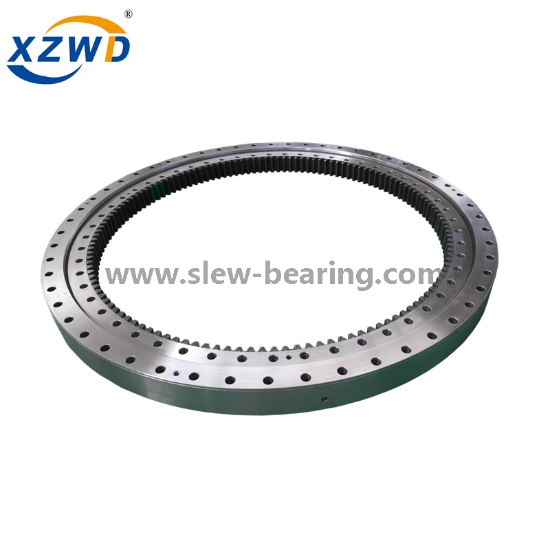
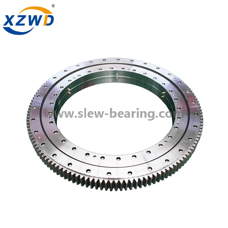
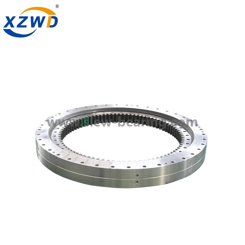
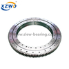
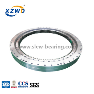
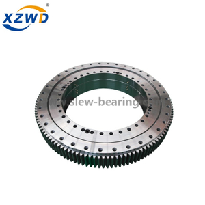
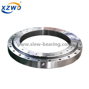
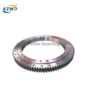
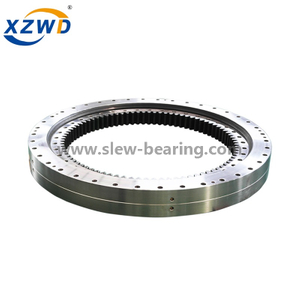
Slewing ring bearing is widely used in harbour crane and shipyard crane for slow-turning under heavy load. As the load situation for harbour crane and shipyard crane is relatively larger, three row roller slewing ring bearing can provide better performance comparing with other structure slewing ring bearing.
In harbour crane and shipyard crane, slewing ring bearing serves as a joint between the upper structure and the undercarriage, providing a means of 360-degree rotation.

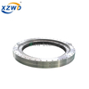
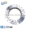
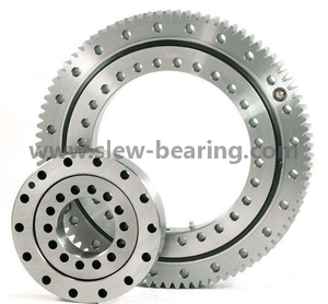
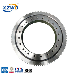
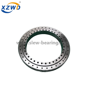
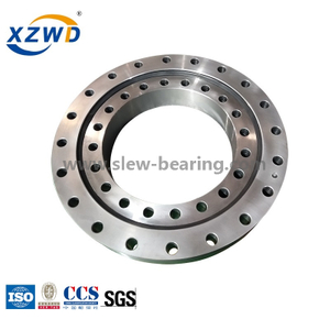
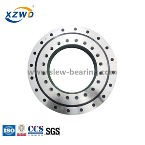
Double row ball slewing bearing has three seat ring, the steel ball and the spacing block can be directly arrange into the upper and lower races, two rows of upper and lower steel balls with differently diameter are fitted according to the stress condition.
Double row different ball slewing bearing's axial and radial size are relatively large and solid in structure, so it is specially fpr the medium diameter tower cranes,truck mounted cranes etc.loading and unloading machinery
Our advantages:
1.Fast delivery
2.Good quality and competitive price
3.Trial order accepted
4.ISO certified company
5.OEM
6. Custom-design is available.
 To get drawing (pdf),please clik on Model.
| No | Model Pdf.format | Dimensions | Mounting Dimension | Structural Dimension | Gear Data | Gear Force | Weight kg | ||||||||||||
| D mm | d mm | H mm | D1 mm | D2 mm | n | mm | n1 mm | H1 mm | h mm | b mm | x | m | D e mm | z | Normalizing Z 104N | Quenching T 104N | |||
| 1 |  023.25.500 023.25.500 | 616 | 384 | 106 | 580 | 420 | 20 | 18 | 4 | 96 | 26 | 60 | 0.5 | 5 | 257 | 72 | 3.7 | 5.2 | 100 |
| 024.25.500 | 6 | 350.4 | 59 | 4.5 | 6.2 | ||||||||||||||
| 2 | 023.25.560 | 676 | 444 | 106 | 640 | 480 | 20 | 18 | 4 | 96 | 26 | 60 | 0.5 | 5 | 417 | 84 | 3.7 | 5.2 | 115 |
| 024.25.560 | 6 | 410.4 | 69 | 4.5 | 6.2 | ||||||||||||||
| 3 | 023.25.630 | 746 | 514 | 106 | 710 | 550 | 24 | 18 | 4 | 96 | 26 | 60 | 0.5 | 6 | 482.4 | 81 | 4.5 | 6.2 | 130 |
| 024.25.630 | 8 | 475.2 | 60 | 6 | 8.3 | ||||||||||||||
| 4 | 023.25.710 | 826 | 594 | 106 | 790 | 630 | 24 | 18 | 4 | 96 | 26 | 60 | 0.5 | 6 | 560.4 | 94 | 4.5 | 6.2 | 140 |
| 024.25.710 | 8 | 555.2 | 70 | 6 | 8.3 | ||||||||||||||
| 5 | 023.30.800 | 942 | 658 | 124 | 898 | 702 | 30 | 22 | 6 | 114 | 29 | 80 | 0.5 | 8 | 619.2 | 78 | 8 | 11.1 | 200 |
| 024.30.800 | 10 | 614 | 62 | 10 | 14 | ||||||||||||||
| 6 | 023.30.900 | 1042 | 758 | 124 | 998 | 802 | 30 | 22 | 6 | 114 | 29 | 80 | 0.5 | 8 | 715.2 | 90 | 8 | 11.1 | 250 |
| 024.30.900 | 10 | 714 | 72 | 10 | 14 | ||||||||||||||
| 7 | 023.30.1000 | 1142 | 858 | 124 | 1098 | 902 | 36 | 22 | 6 | 114 | 29 | 80 | 0.5 | 10 | 814 | 82 | 10 | 14 | 300 |
| 024.30.1000 | 12 | 796.8 | 67 | 12 | 16.7 | ||||||||||||||
| 8 | 023.30.1120 | 1262 | 978 | 124 | 1218 | 1022 | 36 | 22 | 6 | 114 | 29 | 80 | 0.5 | 10 | 924 | 93 | 10 | 14 | 340 |
| 024.30.1120 | 12 | 916.8 | 77 | 12 | 16.7 | ||||||||||||||
| 9 | 023.40.1250 | 1426 | 1074 | 160 | 1374 | 1126 | 40 | 26 | 5 | 150 | 39 | 90 | 0.5 | 12 | 1012.8 | 85 | 13.5 | 18.8 | 580 |
| 024.40.1250 | 14 | 1013.6 | 73 | 15.8 | 21.9 | ||||||||||||||
| 10 | 023.40.1400 | 1576 | 1224 | 160 | 1524 | 1272 | 40 | 26 | 5 | 150 | 39 | 90 | 0.5 | 12 | 1156.8 | 97 | 13.5 | 18.8 | 650 |
| 024.40.1400 | 14 | 1153.6 | 83 | 15.8 | 21.9 | ||||||||||||||
| 11 | 023.40.1600 | 1776 | 1424 | 160 | 1724 | 1476 | 45 | 26 | 5 | 150 | 39 | 90 | 0.5 | 14 | 1349.6 | 97 | 15.8 | 21.9 | 750 |
| 024.40.1600 | 16 | 1350.4 | 85 | 18.1 | 25 | ||||||||||||||
| 12 | 023.40.1800 | 1976 | 1624 | 160 | 1924 | 1676 | 45 | 26 | 5 | 150 | 39 | 90 | 0.5 | 14 | 1545.6 | 111 | 15.8 | 21.9 | 820 |
| 024.40.1800 | 16 | 1542.4 | 97 | 18.1 | 25 | ||||||||||||||
| 13 | 023.50.2000 | 2215 | 1785 | 190 | 2149 | 1851 | 48 | 33 | 8 | 178 | 47 | 120 | 0.5 | 16 | 1702.4 | 107 | 24.1 | 33.3 | 1150 |
| 024.50.2000 | 18 | 1699.2 | 95 | 27.1 | 37.5 | ||||||||||||||
| 14 | 023.50.2240 | 2455 | 2025 | 190 | 2389 | 2091 | 48 | 33 | 8 | 178 | 47 | 120 | 0.5 | 16 | 1942.4 | 122 | 24.1 | 33.3 | 1500 |
| 024.50.2240 | 18 | 1933.2 | 108 | 27.1 | 37.5 | ||||||||||||||
| 15 | 023.50.2500 | 2715 | 2285 | 190 | 2649 | 2351 | 56 | 33 | 8 | 178 | 47 | 120 | 0.5 | 18 | 2203.2 | 123 | 27.1 | 37.5 | 1700 |
| 024.50.2500 | 20 | 2188 | 110 | 30.1 | 41.8 | ||||||||||||||
| 16 | 023.50.2800 | 3015 | 2585 | 190 | 2949 | 2651 | 56 | 33 | 8 | 178 | 47 | 120 | 0.5 | 18 | 2491.2 | 139 | 27.1 | 37.5 | 1900 |
| 024.50.2800 | 20 | 2488 | 125 | 30.1 | 41.8 | ||||||||||||||
| 17 | 023.60.3150 | 3428 | 2872 | 226 | 3338 | 2962 | 56 | 45 | 8 | 214 | 56 | 150 | 0.5 | 20 | 2768 | 139 | 37.7 | 52.2 | 3300 |
| 024.60.3150 | 22 | 2758.8 | 126 | 41.5 | 57.4 | ||||||||||||||
| 18 | 023.60.3550 | 3828 | 3272 | 226 | 3738 | 3362 | 56 | 45 | 8 | 214 | 56 | 150 | 0.5 | 20 | 3168 | 159 | 37.7 | 52.2 | 3700 |
| 024.60.3550 | 22 | 3176.8 | 145 | 41.5 | 57.4 | ||||||||||||||
| 19 | 023.60.4000 | 4278 | 3722 | 226 | 4188 | 3812 | 60 | 45 | 10 | 214 | 56 | 150 | 0.5 | 22 | 3616.8 | 165 | 41.5 | 57.4 | 4200 |
| 024.60.4000 | 25 | 3610 | 145 | 47.1 | 65.2 | ||||||||||||||
| 20 | 023.60.4500 | 4778 | 4222 | 226 | 4688 | 4312 | 60 | 45 | 10 | 214 | 56 | 150 | 0.5 | 22 | 4122.8 | 188 | 41.5 | 57.4 | 4700 |
| 024.60.4500 | 25 | 4110 | 165 | 47.1 | 65.2 | ||||||||||||||
Note:
1. N1 is the numbers of lubricating holes. Oil cup M10×1JB/T7940.1~JB/T7940.
2. The Oil nipple's location can be change according to the user's application.
3. n-φ can change to tapped hole, the diameter of tapped hole is M, and depth is 2M.
4. The tangential tooth force in the form is the max tooth force; the nominal tangential tooth force is 1/2 of the max one.
5. "K" is addendum reduction coefficient.
Slewing ring bearing is widely used in harbour crane and shipyard crane for slow-turning under heavy load. As the load situation for harbour crane and shipyard crane is relatively larger, three row roller slewing ring bearing can provide better performance comparing with other structure slewing ring bearing.
In harbour crane and shipyard crane, slewing ring bearing serves as a joint between the upper structure and the undercarriage, providing a means of 360-degree rotation.
Double row ball slewing bearing has three seat ring, the steel ball and the spacing block can be directly arrange into the upper and lower races, two rows of upper and lower steel balls with differently diameter are fitted according to the stress condition.
Double row different ball slewing bearing's axial and radial size are relatively large and solid in structure, so it is specially fpr the medium diameter tower cranes,truck mounted cranes etc.loading and unloading machinery
Our advantages:
1.Fast delivery
2.Good quality and competitive price
3.Trial order accepted
4.ISO certified company
5.OEM
6. Custom-design is available.
To get drawing (pdf),please clik on Model.
| No | Model Pdf.format | Dimensions | Mounting Dimension | Structural Dimension | Gear Data | Gear Force | Weight kg | ||||||||||||
| D mm | d mm | H mm | D1 mm | D2 mm | n | mm | n1 mm | H1 mm | h mm | b mm | x | m | D e mm | z | Normalizing Z 104N | Quenching T 104N | |||
| 1 | 023.25.500 | 616 | 384 | 106 | 580 | 420 | 20 | 18 | 4 | 96 | 26 | 60 | 0.5 | 5 | 257 | 72 | 3.7 | 5.2 | 100 |
| 024.25.500 | 6 | 350.4 | 59 | 4.5 | 6.2 | ||||||||||||||
| 2 | 023.25.560 | 676 | 444 | 106 | 640 | 480 | 20 | 18 | 4 | 96 | 26 | 60 | 0.5 | 5 | 417 | 84 | 3.7 | 5.2 | 115 |
| 024.25.560 | 6 | 410.4 | 69 | 4.5 | 6.2 | ||||||||||||||
| 3 | 023.25.630 | 746 | 514 | 106 | 710 | 550 | 24 | 18 | 4 | 96 | 26 | 60 | 0.5 | 6 | 482.4 | 81 | 4.5 | 6.2 | 130 |
| 024.25.630 | 8 | 475.2 | 60 | 6 | 8.3 | ||||||||||||||
| 4 | 023.25.710 | 826 | 594 | 106 | 790 | 630 | 24 | 18 | 4 | 96 | 26 | 60 | 0.5 | 6 | 560.4 | 94 | 4.5 | 6.2 | 140 |
| 024.25.710 | 8 | 555.2 | 70 | 6 | 8.3 | ||||||||||||||
| 5 | 023.30.800 | 942 | 658 | 124 | 898 | 702 | 30 | 22 | 6 | 114 | 29 | 80 | 0.5 | 8 | 619.2 | 78 | 8 | 11.1 | 200 |
| 024.30.800 | 10 | 614 | 62 | 10 | 14 | ||||||||||||||
| 6 | 023.30.900 | 1042 | 758 | 124 | 998 | 802 | 30 | 22 | 6 | 114 | 29 | 80 | 0.5 | 8 | 715.2 | 90 | 8 | 11.1 | 250 |
| 024.30.900 | 10 | 714 | 72 | 10 | 14 | ||||||||||||||
| 7 | 023.30.1000 | 1142 | 858 | 124 | 1098 | 902 | 36 | 22 | 6 | 114 | 29 | 80 | 0.5 | 10 | 814 | 82 | 10 | 14 | 300 |
| 024.30.1000 | 12 | 796.8 | 67 | 12 | 16.7 | ||||||||||||||
| 8 | 023.30.1120 | 1262 | 978 | 124 | 1218 | 1022 | 36 | 22 | 6 | 114 | 29 | 80 | 0.5 | 10 | 924 | 93 | 10 | 14 | 340 |
| 024.30.1120 | 12 | 916.8 | 77 | 12 | 16.7 | ||||||||||||||
| 9 | 023.40.1250 | 1426 | 1074 | 160 | 1374 | 1126 | 40 | 26 | 5 | 150 | 39 | 90 | 0.5 | 12 | 1012.8 | 85 | 13.5 | 18.8 | 580 |
| 024.40.1250 | 14 | 1013.6 | 73 | 15.8 | 21.9 | ||||||||||||||
| 10 | 023.40.1400 | 1576 | 1224 | 160 | 1524 | 1272 | 40 | 26 | 5 | 150 | 39 | 90 | 0.5 | 12 | 1156.8 | 97 | 13.5 | 18.8 | 650 |
| 024.40.1400 | 14 | 1153.6 | 83 | 15.8 | 21.9 | ||||||||||||||
| 11 | 023.40.1600 | 1776 | 1424 | 160 | 1724 | 1476 | 45 | 26 | 5 | 150 | 39 | 90 | 0.5 | 14 | 1349.6 | 97 | 15.8 | 21.9 | 750 |
| 024.40.1600 | 16 | 1350.4 | 85 | 18.1 | 25 | ||||||||||||||
| 12 | 023.40.1800 | 1976 | 1624 | 160 | 1924 | 1676 | 45 | 26 | 5 | 150 | 39 | 90 | 0.5 | 14 | 1545.6 | 111 | 15.8 | 21.9 | 820 |
| 024.40.1800 | 16 | 1542.4 | 97 | 18.1 | 25 | ||||||||||||||
| 13 | 023.50.2000 | 2215 | 1785 | 190 | 2149 | 1851 | 48 | 33 | 8 | 178 | 47 | 120 | 0.5 | 16 | 1702.4 | 107 | 24.1 | 33.3 | 1150 |
| 024.50.2000 | 18 | 1699.2 | 95 | 27.1 | 37.5 | ||||||||||||||
| 14 | 023.50.2240 | 2455 | 2025 | 190 | 2389 | 2091 | 48 | 33 | 8 | 178 | 47 | 120 | 0.5 | 16 | 1942.4 | 122 | 24.1 | 33.3 | 1500 |
| 024.50.2240 | 18 | 1933.2 | 108 | 27.1 | 37.5 | ||||||||||||||
| 15 | 023.50.2500 | 2715 | 2285 | 190 | 2649 | 2351 | 56 | 33 | 8 | 178 | 47 | 120 | 0.5 | 18 | 2203.2 | 123 | 27.1 | 37.5 | 1700 |
| 024.50.2500 | 20 | 2188 | 110 | 30.1 | 41.8 | ||||||||||||||
| 16 | 023.50.2800 | 3015 | 2585 | 190 | 2949 | 2651 | 56 | 33 | 8 | 178 | 47 | 120 | 0.5 | 18 | 2491.2 | 139 | 27.1 | 37.5 | 1900 |
| 024.50.2800 | 20 | 2488 | 125 | 30.1 | 41.8 | ||||||||||||||
| 17 | 023.60.3150 | 3428 | 2872 | 226 | 3338 | 2962 | 56 | 45 | 8 | 214 | 56 | 150 | 0.5 | 20 | 2768 | 139 | 37.7 | 52.2 | 3300 |
| 024.60.3150 | 22 | 2758.8 | 126 | 41.5 | 57.4 | ||||||||||||||
| 18 | 023.60.3550 | 3828 | 3272 | 226 | 3738 | 3362 | 56 | 45 | 8 | 214 | 56 | 150 | 0.5 | 20 | 3168 | 159 | 37.7 | 52.2 | 3700 |
| 024.60.3550 | 22 | 3176.8 | 145 | 41.5 | 57.4 | ||||||||||||||
| 19 | 023.60.4000 | 4278 | 3722 | 226 | 4188 | 3812 | 60 | 45 | 10 | 214 | 56 | 150 | 0.5 | 22 | 3616.8 | 165 | 41.5 | 57.4 | 4200 |
| 024.60.4000 | 25 | 3610 | 145 | 47.1 | 65.2 | ||||||||||||||
| 20 | 023.60.4500 | 4778 | 4222 | 226 | 4688 | 4312 | 60 | 45 | 10 | 214 | 56 | 150 | 0.5 | 22 | 4122.8 | 188 | 41.5 | 57.4 | 4700 |
| 024.60.4500 | 25 | 4110 | 165 | 47.1 | 65.2 | ||||||||||||||
Note:
1. N1 is the numbers of lubricating holes. Oil cup M10×1JB/T7940.1~JB/T7940.
2. The Oil nipple's location can be change according to the user's application.
3. n-φ can change to tapped hole, the diameter of tapped hole is M, and depth is 2M.
4. The tangential tooth force in the form is the max tooth force; the nominal tangential tooth force is 1/2 of the max one.
5. "K" is addendum reduction coefficient.


 Español
  简体中文
简体中文