 English
 |


| Quantity: | |
|---|---|
02 and 13 series
xzwd
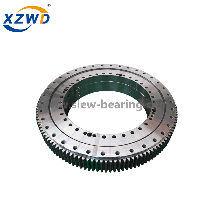
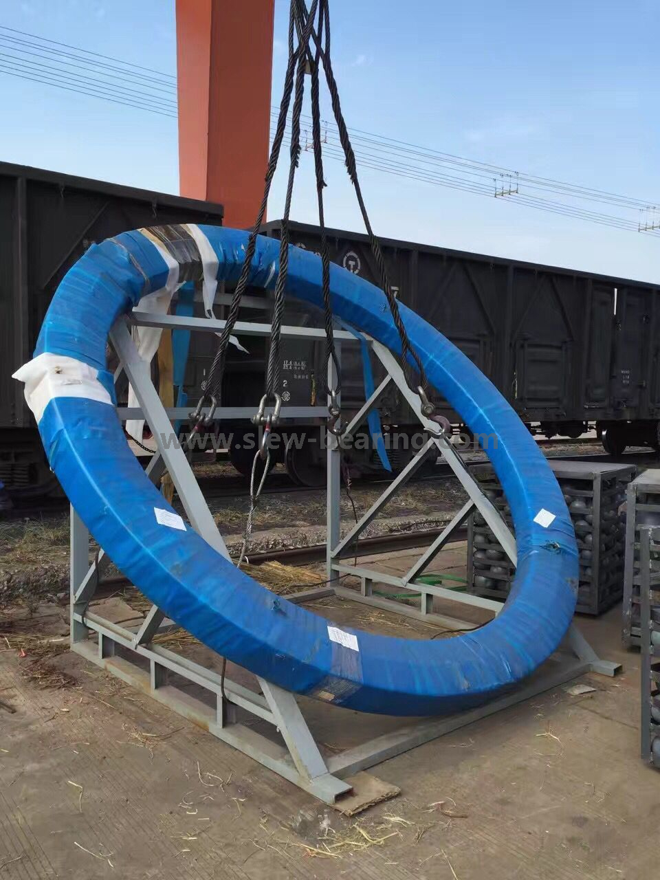
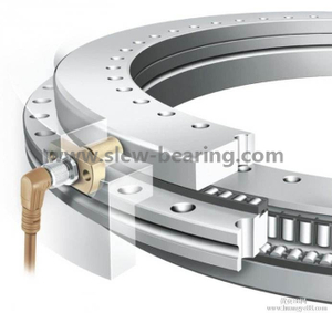
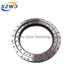
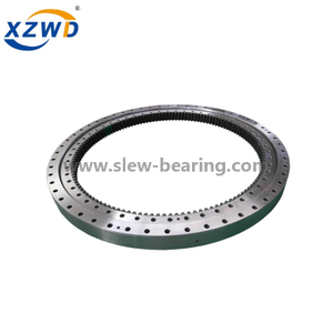
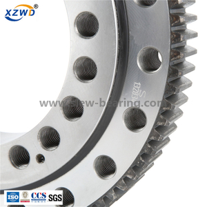
Port Crane used Double row ball and Tree row ball slewing bearing.
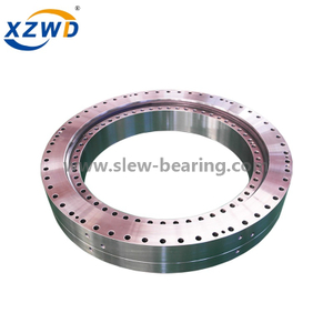
A slewing bearing or slewing ring is a rotational rolling-element bearing or plain bearing that typically supports a heavy but slow-turning or slow-oscillating load, often a horizontal platform such as a conventional crane, a swing yarder, or the wind-facing platform of a horizontal-axis windmill. (To "slew" means to turn without change of place.)
Compared to other rolling-element bearings, slewing bearings are thin in section and are often made in diameters of a metre or more; the slewing bearings on the Falkirk Wheel are 4 metres diameter and fit over a 3.5 metre axle. Slewing bearings resemble oversize aircraft control surface bearings.
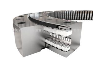
Slewing bearings often use two rows of rolling elements. They often use three race elements, such as an inner ring and two outer ring "halves" that clamp together axially.
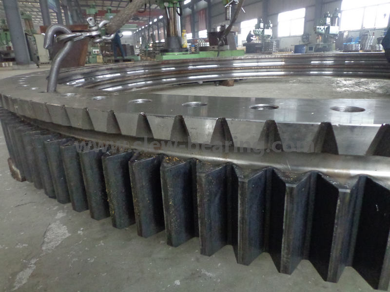
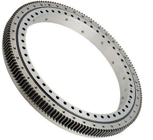
Slewing bearings are often made with gear teeth integral with the inner or outer race, used to drive the platform relative to the base.
As for other bearings that reciprocate, rather than rotating continuously, lubrication can be difficult. The oil wedge built up in a continuously rotating bearing is disrupted by the stop start motion of slewing. Instead, a hydrostatic bearing with pumped oil flow may be used.
Double row ball slewing bearing has three seat ring, the steel ball and the spacing block can be directly arrange into the upper and lower races, two rows of upper and lower steel balls with differently diameter are fitted according to the stress condition.
This kind of open assemly is very convenient, for the upper and lower bear raceway arc angles is 90, which can bear large axial forces and tilting moment. When the radial force is greater than 0.1 times the axial force need to be specially designed the raceway.
Double row different ball slewing bearing's axial and radial size are relatively large and solid in structure, so it is specially fpr the medium diameter tower cranes,truck mounted cranes etc.loading and unloading machinery
Wight/KG:100-4700
 To get drawing (pdf),please clik on Model.
| No | Model Pdf.format | Dimensions | Mounting Dimension | Structural Dimension | Gear Data | Gear circumferential force | Weight kg | ||||||||||||
| D mm | d mm | H mm | D1 mm | D2 mm | n | mm | n1 mm | H1 mm | h mm | b mm | x | m mm | D e mm | z | Normalizing Z 104N | Quenching T 104N | |||
| 1 |  021.25.500 021.25.500 | 616 | 384 | 106 | 580 | 420 | 20 | 18 | 4 | 96 | 26 | 60 | 0.5 | 5 | 644 | 126 | 3.7 | 5.2 | 100 |
| 022.25.500 | 6 | 646.8 | 105 | 4.5 | 6.2 | ||||||||||||||
| 2 | 021.25.560 | 676 | 444 | 106 | 640 | 480 | 20 | 18 | 4 | 96 | 26 | 60 | 0.5 | 5 | 704 | 138 | 3.7 | 5.2 | 115 |
| 022.25.560 | 6 | 706.8 | 115 | 4.5 | 6.2 | ||||||||||||||
| 3 | 021.25.630 | 746 | 514 | 106 | 710 | 550 | 24 | 18 | 4 | 96 | 26 | 60 | 0.5 | 6 | 790.8 | 129 | 4.5 | 6.2 | 130 |
| 022.25.630 | 8 | 790.4 | 96 | 6 | 8.3 | ||||||||||||||
| 4 | 021.25.710 | 826 | 594 | 106 | 790 | 630 | 24 | 18 | 4 | 96 | 26 | 60 | 0.5 | 6 | 862.8 | 141 | 4.5 | 6.2 | 140 |
| 022.25.710 | 8 | 862.4 | 105 | 6 | 8.3 | ||||||||||||||
| 5 | 021.30.800 | 942 | 658 | 124 | 898 | 702 | 30 | 22 | 6 | 114 | 29 | 80 | 0.5 | 8 | 982.4 | 120 | 8 | 11.1 | 200 |
| 022.30.800 | 10 | 988 | 96 | 10 | 14 | ||||||||||||||
| 6 | 021.30.900 | 1042 | 758 | 124 | 998 | 802 | 30 | 22 | 6 | 114 | 29 | 80 | 0.5 | 8 | 1086.4 | 133 | 8 | 11.1 | 250 |
| 022.30.900 | 10 | 1088 | 106 | 10 | 14 | ||||||||||||||
| 7 | 021.30.1000 | 1142 | 858 | 124 | 1098 | 902 | 36 | 22 | 6 | 114 | 29 | 80 | 0.5 | 10 | 1198 | 117 | 10 | 14 | 300 |
| 022.30.1000 | 12 | 1197.6 | 97 | 12 | 16.7 | ||||||||||||||
| 8 | 021.30.1120 | 1262 | 978 | 124 | 1218 | 1022 | 36 | 22 | 6 | 114 | 29 | 80 | 0.5 | 10 | 1318 | 129 | 10 | 14 | 340 |
| 022.30.1120 | 12 | 1317.6 | 107 | 12 | 16.7 | ||||||||||||||
| 9 | 021.40.1250 | 1426 | 1074 | 160 | 1374 | 1126 | 40 | 26 | 5 | 150 | 39 | 90 | 0.5 | 12 | 1497.6 | 122 | 13.5 | 18.8 | 580 |
| 022.40.1250 | 14 | 1495.2 | 104 | 15.8 | 21.9 | ||||||||||||||
| 10 | 021.40.1400 | 1576 | 1224 | 160 | 1524 | 1272 | 40 | 26 | 5 | 150 | 39 | 90 | 0.5 | 12 | 1641.6 | 134 | 13.5 | 18.8 | 650 |
| 022.40.1400 | 14 | 1649.2 | 115 | 15.8 | 21.9 | ||||||||||||||
| 11 | 021.40.1600 | 1776 | 1424 | 160 | 1724 | 1476 | 45 | 26 | 5 | 150 | 39 | 90 | 0.5 | 14 | 1845.2 | 129 | 15.8 | 21.9 | 750 |
| 022.40.1600 | 16 | 1852.8 | 113 | 18.1 | 25 | ||||||||||||||
| 12 | 021.40.1800 | 1976 | 1624 | 160 | 1924 | 1676 | 45 | 26 | 5 | 150 | 39 | 90 | 0.5 | 14 | 2055.2 | 144 | 15.8 | 21.9 | 820 |
| 022.40.1800 | 16 | 2060.8 | 126 | 18.1 | 25 | ||||||||||||||
| 13 | 021.50.2000 | 2215 | 1785 | 190 | 2149 | 1851 | 48 | 33 | 8 | 178 | 47 | 120 | 0.5 | 16 | 2300.8 | 141 | 24.1 | 33.3 | 1150 |
| 022.50.2000 | 18 | 2300.4 | 125 | 27.1 | 37.5 | ||||||||||||||
| 14 | 021.50.2240 | 2455 | 2025 | 190 | 2389 | 2091 | 48 | 33 | 8 | 178 | 47 | 120 | 0.5 | 16 | 2540.8 | 156 | 24.1 | 33.3 | 1500 |
| 022.50.2240 | 18 | 2552.4 | 139 | 27.1 | 37.5 | ||||||||||||||
| 15 | 021.50.2500 | 2715 | 2285 | 190 | 2649 | 2351 | 56 | 33 | 8 | 178 | 47 | 120 | 0.5 | 18 | 2804.4 | 153 | 27.1 | 37.5 | 1700 |
| 022.50.2500 | 20 | 2816 | 138 | 30.1 | 41.8 | ||||||||||||||
| 16 | 021.50.2800 | 3015 | 2585 | 190 | 2949 | 2651 | 56 | 33 | 8 | 178 | 47 | 120 | 0.5 | 18 | 3110.4 | 170 | 27.1 | 37.5 | 1900 |
| 022.50.2800 | 20 | 3116 | 153 | 30.1 | 41.8 | ||||||||||||||
| 17 | 021.60.3150 | 3428 | 2872 | 226 | 3338 | 2962 | 56 | 45 | 8 | 214 | 56 | 150 | 0.5 | 20 | 3536 | 174 | 37.7 | 52.2 | 3300 |
| 022.60.3150 | 22 | 3537.6 | 158 | 41.5 | 57.4 | ||||||||||||||
| 18 | 021.60.3550 | 3828 | 3272 | 226 | 3738 | 3362 | 56 | 45 | 8 | 214 | 56 | 150 | 0.5 | 20 | 3936 | 194 | 37.7 | 52.2 | 3700 |
| 022.60.3550 | 22 | 3933.6 | 176 | 41.5 | 57.4 | ||||||||||||||
| 19 | 021.60.4000 | 4278 | 3722 | 226 | 4188 | 3812 | 60 | 45 | 10 | 214 | 56 | 150 | 0.5 | 22 | 4395.6 | 197 | 41.5 | 57.4 | 4200 |
| 022.60.4000 | 25 | 4395 | 173 | 47.1 | 65.2 | ||||||||||||||
| 20 | 021.60.4500 | 4778 | 4222 | 226 | 4688 | 4312 | 60 | 45 | 10 | 214 | 56 | 150 | 0.5 | 22 | 4879.6 | 219 | 41.5 | 57.4 | 4700 |
| 022.60.4500 | 25 | 4895 | 193 | 47.1 | 65.2 | ||||||||||||||
13 series
Wight/KG:224-7320
To get drawing (pdf),please clik on Model.
No. | External Gear | Dimensions | Mounting Dimension | Structural Dimension | Gear Data | Gear circumferential force | Weight | ||||||||||||||
D | d | H | D1 | D2 | n | mm | dm | L | n1 | H1 | h | b | x | m | D e | z | Normalizing | Quenching | |||
1 | 634 | 366 | 148 | 598 | 402 | 24 | 18 | M16 | 32 | 4 | 10 | 32 | 80 | 0.5 | 5 | 664 | 130 | 5.0 | 6.7 | 224 | |
132.25.500 | 6 | 664.8 | 108 | ||||||||||||||||||
2 | 694 | 426 | 148 | 658 | 462 | 24 | 18 | M16 | 32 | 4 | 10 | 32 | 80 | 0.5 | 5 | 724 | 142 | 5.0 | 6.7 | 240 | |
132.25.560 | 6 | 724.8 | 118 | ||||||||||||||||||
3 | 764 | 496 | 148 | 728 | 532 | 28 | 18 | M16 | 32 | 4 | 10 | 32 | 80 | 0.5 | 6 | 808.8 | 132 | 6.0 | 8 | 270 | |
132.25.630 | 8 | 806.4 | 98 | ||||||||||||||||||
4 | 844 | 576 | 148 | 808 | 612 | 28 | 18 | M16 | 32 | 4 | 10 | 32 | 80 | 0.5 | 6 | 886.8 | 145 | 6.0 | 8 | 300 | |
132.25.710 | 8 | 886.4 | 108 | ||||||||||||||||||
5 | 964 | 636 | 182 | 920 | 680 | 36 | 22 | M20 | 40 | 4 | 10 | 40 | 120 | 0.5 | 8 | 1006.4 | 123 | 12.1 | 16.7 | 500 | |
132.32.800 | 10 | 1008 | 98 | ||||||||||||||||||
6 | 1064 | 736 | 182 | 1020 | 780 | 36 | 22 | M20 | 40 | 4 | 10 | 40 | 120 | 0.5 | 8 | 1102.4 | 135 | 12.1 | 16.7 | 600 | |
132.32.900 | 10 | 1108 | 108 | ||||||||||||||||||
7 | 1164 | 836 | 182 | 1120 | 880 | 40 | 22 | M20 | 40 | 5 | 10 | 40 | 120 | 0.5 | 10 | 1218 | 119 | 15.1 | 20.9 | 680 | |
132.32.1000 | 12 | 1221.6 | 99 | ||||||||||||||||||
8 | 1284 | 956 | 182 | 1240 | 1000 | 40 | 22 | M20 | 40 | 5 | 10 | 40 | 120 | 0.5 | 10 | 1338 | 131 | 15.1 | 20.9 | 820 | |
132.32.1120 | 12 | 1341.6 | 109 | ||||||||||||||||||
9 | 1445 | 1055 | 220 | 1393 | 1107 | 45 | 26 | M24 | 48 | 5 | 10 | 50 | 150 | 0.5 | 12 | 1509.6 | 123 | 22.9 | 31.4 | 1200 | |
132.40.1250 | 14 | 1509.2 | 105 | ||||||||||||||||||
10 | 1595 | 1205 | 220 | 1543 | 1257 | 45 | 26 | M24 | 48 | 5 | 10 | 50 | 150 | 0.5 | 12 | 1665.6 | 136 | 22.9 | 31.4 | 1300 | |
132.40.1400 | 14 | 1663.2 | 116 | ||||||||||||||||||
11 | 1795 | 1405 | 220 | 1743 | 1457 | 48 | 26 | M24 | 48 | 6 | 10 | 50 | 150 | 0.5 | 14 | 1873.2 | 131 | 26.3 | 36.6 | 1520 | |
132.40.1600 | 16 | 1868.8 | 114 | ||||||||||||||||||
12 | 1995 | 1605 | 220 | 1943 | 1657 | 48 | 26 | M24 | 48 | 6 | 10 | 50 | 150 | 0.5 | 14 | 2069.2 | 145 | 26.3 | 36.6 | 1750 | |
132.40.1800 | 16 | 2076.8 | 127 | ||||||||||||||||||
13 | 131.45.2000 | 2221 | 1779 | 231 | 2155 | 1845 | 60 | 33 | M30 | 60 | 6 | 12 | 54 | 160 | 0.5 | 16 | 2300.8 | 141 | 32.2 | 44.5 | 2400 |
132.45.2000 | 18 | 2300.4 | 125 | ||||||||||||||||||
14 | 131.45.2240 | 2461 | 2019 | 231 | 2395 | 2085 | 60 | 33 | M30 | 60 | 6 | 12 | 54 | 160 | 0.5 | 16 | 2556.8 | 157 | 32.2 | 44.5 | 2700 |
132.45.2240 | 18 | 2552.4 | 139 | ||||||||||||||||||
15 | 131.45.2500 | 2721 | 2279 | 231 | 2655 | 2345 | 72 | 33 | M30 | 60 | 8 | 12 | 54 | 160 | 0.5 | 18 | 2822.4 | 154 | 36.2 | 50.1 | 3000 |
132.45.2500 | 20 | 2816 | 138 | ||||||||||||||||||
16 | 131.45.2800 | 3021 | 2579 | 231 | 2955 | 2645 | 72 | 33 | M30 | 60 | 8 | 12 | 54 | 160 | 0.5 | 18 | 3110.4 | 170 | 36.2 | 50.1 | 3400 |
132.45.2800 | 20 | 3116 | 153 | ||||||||||||||||||
17 | 131.50.3150 | 3432 | 2868 | 270 | 3342 | 2958 | 72 | 45 | M42 | 84 | 8 | 12 | 65 | 180 | 0.5 | 20 | 3536 | 174 | 45.2 | 62.6 | 5000 |
132.50.3150 | 22 | 3537.6 | 158 | ||||||||||||||||||
18 | 131.50.3550 | 3832 | 3268 | 270 | 3742 | 3358 | 72 | 45 | M42 | 84 | 8 | 258 | 65 | 180 | 0.5 | 20 | 3936 | 194 | 45.2 | 62.6 | 5680 |
132.50.3550 | 22 | 3933.6 | 176 | 49.8 | 68.9 | ||||||||||||||||
19 | 131.50.4000 | 4282 | 3718 | 270 | 4192 | 3808 | 80 | 45 | M42 | 84 | 8 | 258 | 65 | 180 | 0.5 | 22 | 4395.6 | 197 | 49.8 | 68.9 | 6470 |
132.50.4000 | 25 | 4395 | 173 | 56.5 | 78.3 | ||||||||||||||||
20 | 131.50.4500 | 4782 | 4218 | 270 | 4692 | 4308 | 80 | 45 | M42 | 84 | 8 | 258 | 65 | 180 | 0.5 | 22 | 4901.6 | 220 | 49.8 | 68.9 | 7320 |
132.50.4500 | 25 | 4895 | 193 | 56.5 | 78.3 | ||||||||||||||||
Note:
1. N1 is the numbers of lubricating holes. Oil cup M10×1JB/T7940.1~JB/T7940.
2. The Oil nipple's location can be change according to the user's application.
3. n-φ can change to tapped hole, the diameter of tapped hole is M, and depth is 2M.
4. The tangential tooth force in the form is the max tooth force; the nominal tangential tooth force is 1/2 of the max one.
5. "K" is addendum reduction coefficient.


 Español
  简体中文
简体中文